


Led Matrix Red 8×8 (1088AS)
Original price was: 32.49 EGP.30.00 EGPCurrent price is: 30.00 EGP.
Only 1 left in stock
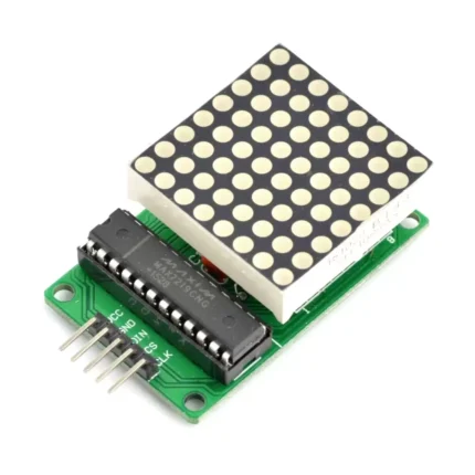
Led Matrix Red 8×8 (1088AS) is a high-quality electronic component designed for Arduino, prototyping, and educational electronics. 8X8 LED MATRIX Pin Configuration
LED MATRIX MODULES are available in different modules and each module will have different pin configuration. Here we have shown the pin configuration of 1388A LED matrix module . Different modules may have different pinout configuration but they have same functioning pins.
Pin Number
Description
NEGATIVE TERMINALS
1
PIN1 is taken out from 4th COLUMN
2
PIN2 is taken out from 2nd COLUMN
5
PIN5 is taken out from 1st COLUMN
7
PIN7 is taken out from 3rd COLUMN
8
PIN8 is taken out from 6th COLUMN
9
PIN9 is taken out from 8th COLUMN
12
PIN12 is taken out from 5th COLUMN
14
PIN14 is taken out from 7th COLUMN
POSITIVE TERMINALS
3
PIN3 is taken out from 2nd ROW
4
PIN4 is taken out from 3rd ROW
6
PIN6 is taken out from 5th ROW
10
PIN10 is taken out from 4th ROW
11
PIN11 is taken out from 6th ROW
13
PIN13 is taken out from 1st ROW
15
PIN15 is taken out from 7th ROW
16
PIN16 is taken out from 8th ROW
As given in above table, any 8×8 LED MATRIX will have EIGHT POSITIVE TERMINALS and EIGHT NEGATIVE TERMINALS.
EIGHT NEGATIVE TERMINALS are EIGHT COLUMNS.
EIGHT POSITIVE TERMINALS are EIGHT ROWS.
These 16 PINS are driven out from 64 LED SEGMENTS present in the MODULE. Those 64 SEGMENTS on the MODULE surface are the 64 LEDS arranged in MATRIX formation.
The internal structure of any LED MATRIX MODULE will be same and is shown below.
Note: More technical information can be found in the LED Matrix Datasheet linked at the bottom of this page.
How to solve PIN CONFIGURATION Issue
As shown above, the POSITIVE and NEGITIVE PINS of MATRIX MODULE are irregular and may lead to problems while controlling the LEDs. This issue becomes even more complex when choosing a different MODULE. The best way to solve these problems is rearrange the terminals based on FUNCTION of PIN instead of PIN NUMBER. After rearranging the PINS, we will have something as below.
As shown in figure, by rearranging the EIGHT ROWS or POSITIVE and EIGHT COLUMNS or NEGATIVE we can completely eliminate the problem of PIN CONFIGURATION. As every module will have same ROWS and COLUMN even if MODULE outlets are random.
8×8 LED MATRIX MODULE Features and Specifications
Forward Voltage for EACH SEGMENT or LED turning ON: 1.5V-2.0V (2.0V being absolute maximum forward voltage)
EACH SEGMENT or LED Forward Current during ON: 10mA – 15mA (Typically 10mA, 15mA being absolute maximum forward current)
EACH SEGMENT or LED Reverse Voltage Maximum: 5V
Maximum operating temperature: – 25°C to + 60°
Where to Use 8×8 LED MATRIX MODULE
8×8 LED MATRIX MODULE is used for various purpose; we can point a few:
Case1: When the cost is of issue. LED MATRIX could be considered the cheapest of all DISPLAY devices present on market
Case2: When there is a need for displaying ALPHABETS and CUSTOM characters. Although MATRIX MODULE can only display ONE character at a time, Displaying CUSTOM characters in it are easy and simple.
Case3: LED MATRIX MODULE can basically perform any display function like GAMING and GRAPHICS. Since MATRIX MODULE is controlled PIXEL by PIXEL, performing GRAPHICS functions is simple
Case4: When display is used at OUTDOORS. LCD displays are basically useless at outdoors since the characters are barely visible. The LED MATRIX MODULE illumination is visible under daylight unlike LCD and GRAPHIC displays, so for outdoors using LED MATRIX MODULE is ideal.
How to Use 8×8 LED MATRIX MODULES
Using LED MATRIX is easy; all you need to power the appropriate segment to turn it on. These 64 LEDs in the MATRIX will be tuned ON by appropriately powering the 16 output pins. For turning them ON, we need to provide +1.5V to appropriate ROW and GROUND the appropriate COLUMN.
As shown above, we tuned ON a segment (LED) placed on FOURTH ROW and THIRD COLUMN. For turning it ON we have taken a +1.5v voltage source and connected the POSITIVE terminal to ROW4 PIN (FOURTH ROW pin) and NEGATIVE terminal to C3 PIN (THIRD COLUMN pin ). When the connections are done, the voltage source forms a closed loop with that LED SEGMENT tuning it ON.
Consider we want to turn ON a segment (LED) placed on SECOND ROW and EIGHTH COLUMN. All we need to do is connect the POSITIVE terminal of voltage source to ROW2 PIN and NEGATIVE terminal to C8 PIN. With the power being provided that LED will turn ON.
In this LED MATRIX MODULE we have overlapping issue. Consider a case where you want to turn two LEDs (marked by RED) in MATRIX. We need Powering both R3, R4 and grounding both C4, C5. With that two additional LEDs (marked by GREEN) will glow along with the required ones. This issue will be solved by MULTIPLEXING and is discussed previously. With MULTIPLEXING we can use MATRIX MODULE conveniently.
Applications
OUTDOOR displays
POSTER display
PIXEL gaming
Character design
Measuring instruments
Hobby projects
2D Model and Dimensions
All measurements are given in millimeters.
Component Datasheet
8×8 LED Matrix Datasheet It’s perfect for DIY makers, students, and anyone building custom electronic circuits or STEM kits.