
IMU 6-DOF MPU-6050 Sensor Module
Original price was: 172.01 EGP.150.00 EGPCurrent price is: 150.00 EGP.
Axis analog gyro sensors+ 3 Axis Accelerometer Module
The MPU-6050 is the latest product of InvenSense company products. This sensor is used in Ardupilot autopilot. The sensor contains a 3-axis MEMS accelerometer and a 3-axis MEMS gyro in a single chip. It is very accurate since it contains 16-bit analog to digital-conversion hardware for each channel. Therefore it captures the x, y, and z channels at the same time.
Also, it is accurate because you have the 3-axis gyro and 3-axis accelerometers on a single chip so you do not need to align them.
The sensor has a “Digital Motion Processor” (DMP), also called a “Digital Motion Processing Unit”. This DMP can be programmed with firmware made by Innisense and can do complex calculations with the sensor values.
Features
- I2C Digital output of 6 or 9-axis MotionFusion data in rotation matrix, quaternion, Euler Angle, or raw data format
- Input Voltage: 2.3 – 3.4V.
- Tri-axis angular rate sensor (gyro) with a sensitivity of up to 131 LSBs/dps and a full-scale range of ±250, ±500, ±1000, and ±2000dps.
- Tri-Axis accelerometer with a programmable full-scale range of ±2g, ±4g, ±8g and ±16g
- Digital Motion Processing™ (DMP™) engine offloads complex MotionFusion, sensor timing synchronization, and gesture detection.
- Digital-output temperature sensor.
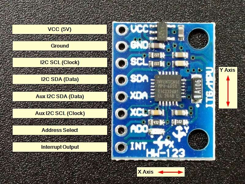
MPU6050 Pinout Configuration
| Pin Number | Pin Name | Description |
| 1 | Vcc | Provides power for the module, which can be +3V to +5V. Typically +5V is used |
| 2 | Ground | Connected to the Ground of the system |
| 3 | Serial Clock (SCL) | Used for providing clock pulse for I2C Communication |
| 4 | Serial Data (SDA) | Used for transferring Data through I2C communication |
| 5 | Auxiliary Serial Data (XDA) | Can be used to interface other I2C modules with MPU6050. It is optional |
| 6 | Auxiliary Serial Clock (XCL) | Can be used to interface other I2C modules with MPU6050. It is optional |
| 7 | AD0 | If more than one MPU6050 is used a single MCU, then this pin can be used to vary the address |
| 8 | Interrupt (INT) | Interrupt pin to indicate that data is available for MCU to read. |
Where to Use MPU6050
The MPU6050 is a Micro-Electro-Mechanical System (MEMS) that consists of a 3-axis Accelerometer and 3-axis Gyroscope inside it. This helps us to measure acceleration, velocity, orientation, displacement, and many other motion-related parameters of a system or object. This module also has a (DMP) Digital Motion Processor inside it which is powerful enough to perform complex calculations and thus free up the work for Microcontroller.
The module also has two auxiliary pins which can be used to interface external IIC modules like a magnetometer, however, it is optional. Since the IIC address of the module is configurable more than one MPU6050 sensor can be interfaced to a Microcontroller using the AD0 pin. This module also has well-documented and revised libraries available hence it’s very easy to use with famous platforms like Arduino. So if you are looking for a sensor to control motion for your RC Car, Drone, Self-balancing Robot, Humanoid, Biped, or something like that then this sensor might be the right choice for you.
How to Use MPU6050 Sensor
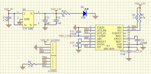
The hardware of the module is very simple, it comprises the MPU6050 as the main component as shown above. Since the module works on 3.3V, a voltage regulator is also used. The IIC lines are pulled high using a 4.7k resistor and the interrupt pin is pulled down using another 4.7k resistor.
The MPU6050 module allows us to read data from it through the IIC bus. Any change in motion will be reflected on the mechanical system which will in turn vary the voltage. Then the IC has a 16-bit ADC which it uses to accurately read these changes in voltage and stores it in the FIFO buffer and makes the INT (interrupt) pin to go high. This means that the data is ready to be read, so we use a MCU to read the data from this FIFO buffer through IIC communication. As easy as it might sound, you may face some problem while actually trying to make sense of the data. However there are lots of platforms like Arduino using which you can start using this module in no time by utilizing the readily available libraries explained below.
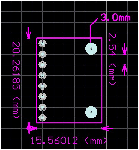
2D Model of MPU6050
Applications
- Used for IMU measurement
- Drones / Quadcopters
- Self-balancing robots
- Robotic arm controls
- Humanoid robots
- Tilt sensor
- Orientation / Rotation Detector